1:Download Dumps
2:Download E-Book
| ||||||||||||||
This information get from some forums (sadikhov..) , I dont know it correct or not correct, you should thinks by yourseft.
Hi all
I have ONT with 1000/1000. So Glad and now CCNP Certified.
P4S 2.95 still valid, All simlets is been discussed.
Didnt have to go through the new security measures. I did my exam in Syd, Aus.
Good luck all, and big thanks to Sadikhov and all members for great shares.
hi guys, i passed ont today
about 7-8 new questions but they were pretty easy.. nothing to worry about
and most of the questions came from this topic not from p4s .95 :-)
so dont forget to take a look at discussed questions in this topic
Guys I passed with 1000/1000 Yesterday
I apprichiate the effort of all who sharing there experience
all from pass4sure 2.95 except one sim Citrix , SQL Net simlet mentioned before
I pass ONT today with 955 score.4-5 were out of p4s 2.95.
thx to all sakikhov member and sadikhov forever!I like you guy!
New quetions encountered:
An exhibit showing 3 Remote sites B, C, and D connected to a Central Site A via a Frame Relay connection. Links A, B,C and D are T1, 128k, 512k and 768k respectively.
Q1: Refer to the exhibit. Which two points would traffic shaping and traffic policing best be applied?(Choose 2)
A.Central Site – apply traffic shaping inbound so that the central router and servers will not experience congetion.
B.Central Site – apply traffic policing outbound so that the link speed will match the link speed of the remote sites.
C.Remote Site – apply traficc shaping inbound so that the traffic coming from the central site does not cause congestion in the remote network.
D.Remote Site – apply traficc shaping outbound so that the remote links are not oversubscribed.
E.Remote Site – apply traficc shaping outbound so that packets are prioritid and packets that are received in excess are dropped.
Answers: A,D
Q2: Drag the steps required to convert analog to digital signaling on the left to the correct order on the right.
A.Decompression
B.Encoding
C.Quantization
D.Sampling
E.Compression
F.Reconstruction
Answers: Step1=D, Step 2=C, Step 3=B (i.e Sampling, Quantization, and Ecoding)
Q3: Which two characteristics are common between traffic policing and traffic shaping (choose 2).
A.The rate of traffic is measured and compared to a configured policy.
B.Classification is used to differentiate traffic.
C.Traffic is marked and sent out according to priority.
D.Both can be applied to inbound and outbound traffic.
Answers: A, B
Only 3 questions came out from p4s.
Q1 the simlet..... as it mentioned by many of our friends
1.the mission critical trafic in wlan => SQLNET
2.issue on wan2 => wrong polict the correct should be policy 1
3.is ftp being marked correctly => yes ftp is marked correctly based on NBAR
4.the af21 => CITRIX
Q2.there were 4 routers A,B,C,andD connected with frame relay cloud.the question was where to apply inbound and out bound policy(choose two)
answers...
*inbound at remote site
*outboundat central site
Q3.showed a wlc exhibit?(choose three)
answers....
* add new lightweight access point
* locate rouge access point
* show mac address from rouge access point
This information get from some forums, I dont know it correct or not correct, you should thinks by yourseft.
Hey Every one i passed BCMSN 1000/1000
2 labs from p4s
2 simlet 1 HSRP not in p4s, stp in p4s
2 drag and drop from p4s
2 question out of p4s
First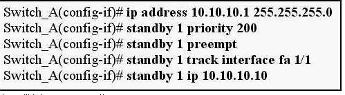
Which configuration is required on Neighbor HSRP router, in case of event of Failure of interface Fa 1/1 on swich A
The answer is
Option C
Switch_B(config-if)#ip address 10.10.10.1 255.255.255.0
Switch_B(config-if)#standby 1 priority 195
Switch_B(config-if)#standby 1 preempt
Switch_B(config-if)#standby 1 ip 10.10.10.10
Second
one multilayer switch configuration which was connected with 2 access layer switch trunk configured the question is why vlan 100 is not able to ping vlan 200 ,
The anwser was to enable Ip routing
other questions from p4s sure like 13,14,15,17,22,24,26,28,31,33,35,36,38,45,50,58,67,70,75,76,77,85,87,89,93,98,99
,101,102,111,112,117,125,126,127,136,143,144,,149,155,158,161,,164 etc
The Version is used was p4s 2.93
TODAY, i have passed bcmsn test (642-812) with pass-score 988 out 1000
I want tell everyone who intend to have the exam not to worry
Firstly p4s version 2.93 is the last updated and you can make sure from p4s website (286 q.)
Secondly the exam was an exact copy of the p4s and there is no new question i have faced except my first one which was HSRP SIMLET (6 multiple choices given the topolgy and the console access to the switches)
You can find in this forum 5 of 6 question in this forum, the sixth question was:
-for vlan 104: when gi1/0/1 is down on both swithces sw1 will be the active router whereas it was intended that sw2 will be the active one so what is the problem ?!
when u check using show stand by command that the tracking command is enabled with the pre-empt command so when the interface is going down the priority of the sw2 for vlan 104 will be decreased than the one in the
sw1 so the solution is to disable the preemption on sw1.
Hi,
Its very easy just use "show standby" comand
HSRP simlet:
1. For the vlan 102: active vlan is DSW-1, what is the priority of DSW-2? When look at the conf by clicking the DSW-2 icon you can see priority is no explicitly defined at DSW-2 so priority is 100 for vlan2.
2. For the vlan 101: active vlan is DSW01, and gi 1/0/1 goes down at DSW-1 but DSW-1 still active for vlan 101, how can we fix that problem? When look at the configurations DSW-1 priority is 200 for vlan 101, DSW-2's is 190. DSW-1 is tracking gi 1/0/1 interface with decrement value 5. so we should change the decrement value from 5 to 15.
3. For the vlan 103: active vlan is DSW-1, priority is 150 and is tracking gi 1/0/1 interface with decrement value 55. What is the new priority for DSW-1 when gi 1/0/1 is gone? Answer is 95.
4. For the vlan 105: active vlan is DSW-2, when tracking interface gi 1/0/1 at DSW-2 is gone active switch would be DSW-1. But when coming back the interface gi 1/0/1 back DSW-1 is still active sw dor vlan 105, what is the problem? You should enter preemt commant at DSW-2.
5. dsw1 is active for 103 vlan, dsw2 is not active even if all interface are up -- bcos priority on dsw1 is 200 and dsw2 is 190 - so decrease priority on dsw1 switch betw 150 and 190
LAP 1: PPPoE


Config :
P4S-R(config)#int e0/0
P4S-R(config-if)#pppoe enable
P4S-R(config-if)#pppoe-client dial-pool-number 1
P4S-R(config-if)#no sh
P4S-R(config-if)#exit
P4S-R(config)#int dialer1
P4S-R(config-if)#encapsulation ppp
P4S-R(config-if)#ip address negotiated
P4S-R(config-if)#dialer pool 1
P4S-R(config-if)#ip mtu 1492
P4S-R(config-if)#no shut
P4S-R(config-if)#exit
P4S-R(config)#ip route 0.0.0.0 0.0.0.0 dialer1 <---- ip routing is default static to internet provider
P4S-R#copy run start
The test ip address given in the scenario:
P4S-R# ping 172.16.1.1
!!!!! <----- if ping successful, you have completed this lab!
LAP 2: TACACS+
A company in installed new router R1 in their network. As a administrator you need to configure TACACS for the router with following configuration given below.
1. Enable the TACACS server in R1
2. Configure console and Aux for default authentication
3. Cinfigure VTY for TACACS server authentication
4. Configure the Tacacs server ip 10.2.2.2 and share key 123
5. Login to R2 using provided username and password ( username R2, password COL )
6. From R2 login to R1 using SSH and check the R1 TACACS ( username R1, Passwork TAC )

Config :
R1(Config)# aaa new-model
R1(Config)# tacacs-server host 10.2.2.2 key 123 ( IP and Key may change)
R1(Config)# aaa authentication login default local
R1(Config)# aaa authentication login CUSTOM_LIST group tacacs+ ( Only required to allow TACACS )
R1(Config)# line console 0
R1(Config)# login authentication default
R1(Config)# line aux 0
R1(Config)# login authentication default
R1(Config)# line vty 0 4
R1(Config)# login authentication CUSTOM_LIST
R1(Config)# line vty 5 15
R1(Config)# login authentication CUSTOM_LIST
R1(Config)# exit
R1# copy run start
Login to R2 with provided credentials.
R2>username R2
R2>pass : COL
R2# ssh -l 192.168.1.1 ( It should be successful !!!)
LAP 3: VNP site to site GRE with EIGRP

This is question that request you must click into console to check configure and then answer . Cisco has changed a lot questions in this lap. A Lot of people take the exam and anybody like own. So, I cant post answers in here. You should understand well about VPN GRE tunnel, GRE with EIGRP ... Good luck for the exam !!!
Hotspot 1: IOS Firewall and ACL


Hotspot 2 : Site to site IPSEC VPN

Question & Answer 1

Solution :


Question & Answer 2

Solution :


Question & Answer 3, 4 :


Solution :


The new question, out of P4S 3.10:
New question 1: BGP

Router B and C have establisted LDP nei session. During troubleshoot, the labels are being distributed in between 2 router B & C. But no label swapping information in LFIP table. What is most likely cause ?
A. Not yet enable CEF on all router.
B. Not yet run IGP between core-routers
C. Create wrong vrf for every customer.
D. LDP Router-id of this router but point LDP router-id of another router.
New question 2: GRE Tunnel

Why the HostA can NOT ping Server1 ???
A. The tunnel number is diffirent on two router
B. Router 1 have configured wrong tunnel source
C. Router 1 have configured wrong tunnel destination
D. Router 2 have configured wrong tunnel source
Corrected Question from P4S
Question 176 ( p4s 3.10)

A is correct. The question 11 is the same, but answer wrong. ACL 100 ( trusted int ), ACL 101 (untrusted int).
Question 270 ( p4s 3.10)

C, E is correct. The same question, but in p4s answer : The IPS enables a dysnamic acccess list is wrong.
Question 287 ( p4s 3.10)

The answer in p4s is wrong. Config GRE tunnel, you should have "tunnel source" command.
Question 261 ( p4s 3.10)
Drag and drop the steps in the process for provisioning a cable modem to connect to a headend on the above to the below in the order defined by the DOCSIS standard.

The answer in P4S is wrong. The item "IP network initialization" should put at the end.
Hotspot 1 : super HSRP question
- DS1( Distribute switch 1) is the primary device for Vlan 101, 102, 105
- DS2 ( Distribute switch 2) is the primary device for Vlan 103 and 104

Question 1:
During routine maintenance, it became necessary to shutdown G1/0/1 on DS1. All other interface were up. During this time, DS1 remained the active device for Vlan 102's HSRP group. You have determined that there is an issue with the decrement value in the track command in Vlan 102's HSRP group. What need to be done to make the group function properly ?
A. The DS1's decrement value should be configured with a value from 5 to 15
B. The DS1's decrement value should be configured with a value from 9 to 15
C. The DS1's decrement value should be configured with a value from 11 to 18
D. The DS1's decrement value should be configured with a value from 195 to less than 205
E. The DS1's decrement value should be configured with a value from 200 to less than 205
F. The DS1's decrement value should be greater than 190 and less 200
Explanation:

Use "show run" command to show. The left Vlan102 is console1 of DS1. Priority value is 200, we should decrement value in the track command from 11 to 18. Because 200 - 11 = 189 <>
Question 2:
During routine maintenance, G1/0/1 on DS1 was shutdown. All other interface were up. DS2 became the active HSRP device for Vlan101 as desired. However, after G1/0/1 on DS1 was reactivated. DS1 did not become the active HSRP device as desired. What need to be done to make the group for Vlan101 function properly ?
A. Enable preempt on DS1's Vlan101 HSRP group
B. Disable preempt on DS1's Vlan101 HSRP group
C. Decrease DS1's priority value for Vlan101 HSRP group to a value that is less than priority value configured on DS2's HSRP group for Vlan101
D. Decrease the decrement in the track command for DS1's Vlan 101 HSRP group to a value less than the value in the track command for DS2's Vlan 101 HSRP group.
Explanation:

A is correct. All other answers is incorrect. Because Vlan101 on DS1 ( left ) disable preempt. We need enable preempt to after it reactive , it will be active device. If not this command, it never become active device.
Question 3:
DS2 has not become the active device for Vlan103's HSRP group even though all interfaces are active. As related to Vlan103's HSRP group. What can be done to make the group function properly ?
A. On DS1, disable preempt
B. On DS1, decrease the priority value to a value less than 190 and greater than 150
C. On DS2, increase the priority value to a value greater 241 and less than 249
D. On DS2, increase the decrement value in the track command to a value greater than 10 and less than 50.
Explanation:
( update soon ....)
Question 4:
If G1/0/1 on DS1 is shutdown, what will be the current priority value of the Vlan105's group on DS1 ?
A. 95
B. 100
C. 150
D. 200
Explanation:

Priority is configured 150, Track is 55. So, if shutdown interface G1/0/1 --> 150 - 55 = 95.
Question 5:
What is the configured priority value of the Vlan105's group on DS2 ?
A. 50
B. 100
C. 150
D. 200
Explanation:

Use "show stantby brieft" command on console2 . Very easy to see priority of Vlan105 is 100.
Question 6:
During routine maintenance, it became necessary to shutdown G1/0/1 on DS1 and DS2. All other interface were up. During this time, DS1 became the active device for Vlan104's HSRP group. As related to Vlan104's HSRP group. What can be done to make the group function properly ?
A. On DS1, disable preempt
B. On DS2, decrease the priority value to a value less than 150
C. On DS1, increase the decrement value in the track command to a value greater than 6
D. On DS1, disable track command.
Explanation:

We should NOT disable preempt on DS1. By do that, you will make Vlan104's HSRP group fail function. Example: if we are disable preempt on DS1. It can not become active device when G1/0/1 on DS2 fail. In this question, G0/1/0 on DS1 & DS2 is shutdown. Vlan104 (left) : 150 - 1 = 149. Vlan104 (right) : 200 - 155 = 145. Result is priority 149 > 145 ( Vlan104 on DS1 is active). If increase the decrement in the track value to a value greater than 6 ( > or = 6). Vlan104 (left) : 150 - 6 = 144. Result is priority 144 <>
Question 7:
Which statement is correct about the use of the virtual interface on a WLC :
A. Used to relay DHCP messages
B. Used to communicate with LAPs
C. Used to bring up LWAPP tunnels
D. Used to extend into the wireless client VLAN
Hotspot 2 : OSPF
The company and the company network have both been growing rapidly. Multiple adds, moves and changes have been applied to the network. Your boss at Certkiller .com, Miss Certkiller, has asked you to troubleshoot a recent OSPF synchronization problem that has arisen. There have been synchronization problems at separate locations in the OSPF area 0. There have been reported link failures during the rapid growth of the company network. You are required to resolve the OSPF problem. OSPF must be able to converge when the network changes.
Refer to the information above to answer the following 4 questions:

Question 1 :
Examine the following excerpt from the "show ip ospf" command on Certkiller A:
Area BACKBONE (0)
Number of interfaces in the this area is 1
Area has no authentication
SPF algorithm last executed 00:00:31.280 ago
SPF algorithm executed 5 times
Area ranges are
Number of LSA 13. Checksum Sum 0x16F0FD
Number of opaque link LSA 0. Checksum Sum 0x000000
Number of DCbitless LSA 0
Number of indication LSA 0
Number of DoNotAge LSA 0
Flood list length 0
Area 16
Number of interfaces in this area is 2
Area has message digest authentication
SPF algorithm last executed 00:00:34.928 ago
SPF algorithm executed 7 times
Area ranges are
Number of LSA 5. Checksum Sum 0x02FCD3
Number of opaque link LSA 0. Checksum Sum 0x000000
Number of DCbitless LSA 0
Number of indication LSA 0
Number of DoNotAge LSA 0
Flood list length 0
Based on the information shown above, what is most likely causing the different missing routes throughout the network?
A. Area 16 is configured with authentication.
B. Area 16 has been configured to use the same interfaces as Area 0.
C. Area 0 and Area 32 have been configured with mismatched LSA numbers.
D. Area 16 has been configured as a total stub network
E. Area 16 has been configured as a stub network
F. Area 0 is discontiguous.
G. None of the above
Explanation:
In this example, Certkiller1 shows that it only has 1 interface in area 0, while the network diagram shows that there should be two. This means that the Fa0/1 link is most likely gone down, creating a discontiguous backbone area. The link needs to be restored, or a virtual link needs to be created to fix this.
Question 2 :
Which configuration command on Certkiller 1 (with a similar command on Certkiller 2) will provide an immediate solution to the missing route problem?
A. no area 16 stub
B. no area 16 authentication message-digest
C. area 16 virtual-link 8.187.175.82
D. area 16 virtual-link 172.16.4.2
E. no area 16 stub no-summary
F. network 172.16.0.0.0.0.255.255 area 16
G. None of the above
Explanation:
A virtual link to an IP address (the loopback IP address in this case) on device Certkiller2 needs to be created. Similarly,Certkiller2 needs to also have this configured so that a virtual link to area 0 from area 16 can be created
Question 3:
The log of Certkiller 1 reports the following:
%LINEPROTO-5-UPDOWN: Line protocol on Interface FastEthernet0/1, changed state to down
%LINK-3-UPDOWN: Interface FastEthernet0/1, changed state to down
%OSPF-5-ADJCHG: Process 1, Nbr 8.187.175.82/32 on FasstEthernet0/1 from FULL to DOWN,
Neighbor Down: Interface down or detached
This event was anticipated due to maintenance; however, it resulted in excessive lost routes. Which route should be the only one removed from the routing tables of the routers?
A. 8.187.175.82/32
B. 10.138.43.0/30
C. 10.206.180.0/30
D. 4.249.113.59/32
E. 10.201.0.0/30
F. None of the above
Explanation:
The FastEthernet 0/1 link was the only physical link that went down, so in this case the network administrator had meant to only remove the 10.201.1.10/30 route associated with that link. However, the loopback IP address of Certkiller 2 is 8.187.175.82/32, which means that the neighbor relationship is down. When the FE 0/1 interface goes down, area 0 will effectively be cut in half creating a discontiguous backbone area.
Question 4:
The Certkiller 2 Router has lost connectivity to Certkiller 1. The following is Certkiller 1's current route table:
172.16.0.0/16 is variably subnetted, 3 subnets, 2 masks
O IA 172.16.240.0/24 [110/11] via 10.218.67.1, 00:00:03, FastEthernet0/0
O IA 172.16.209.0/24 [110/12] via 10.218.67.1, 00:00:03, FastEthernet0/0
O IA 172.16.4.0/30 [110/2] via 10.218.67.1, 00:00:03, FastEthernet0/0
10.0.0.0/30 is subnetted, 1 subnets
C 10.218.67.0 is directly connected, FastEthernet0/0
Which expected route is missing from Certkiller 1's route table based on the topology during the maintenance period?'
A. o 172.16.0.0 [110/2] via 10.218.67.1, 00:00:09, FastEthernet0/0
B. o IA 9.152.105.122 [110/3] via 10.218.67.1, 00:00:09, FastEthernet0/0
C. o IA 10.138.0.0 [110/3] via 10.218.67.1, 00:00:09, FastEthernet0/0
D. o IA 10.249.0.0 [110/2] via 10.218.67.1, 00:00:09, FastEthernet0/0
E. o IA 4.249.113.59 [110/2] via 10.218.67.1, 00:00:09, FastEthernet0/0
F. o 8.187.175.82 [110/3] via 10.218.67.1, 00:00:09, FastEthernet0/0
Explanation:
In this case, the missing route is the route to the loopback IP address of Certkiller 2. This loopback IP address was used for the virtual link, which was needed when the backbone area became discontiguous. If this route was missing, the virtual link would then go down and cause the additional routes to be missing.
Hotspot 3 : Spanning Tree

You study the network topology carefully, see exhibit. Then you connect to the SW-c ; issue the show spanning tree command. Please refer to the exhibit for the output. You are then required to answer the scenario questions using the information that is available.


Question 1:
Which spanning Tree Protocol has been implemented on SW-B?
A. STP/IEEE 802.1D
B. MSTP/IEEE 802.1s
C. PVST+
D. PVRST
E. None of the above
Explanation:
802.1D has not been implemented since this is CST (Common Spanning Tree) which only allows one instance to be run at a time per Network. In this scenario there are multiple instances. It must be PVST+ since each instance only contains one VLAN.
Question 2:
Which bridge ID belongs to SW-B?
A. 32928 000d bd33 029b
B. 24623 000f 34f5 039b
C. 32928 000d bd03 029b
D. 32768 000d bd33 029b
E. 32769 000d 65db 01dd
F. 32815 000d bd03 029b
Explanation:
Root ports are ports that point to the Root Bridge. In the exhibit, under VLAN 47 we see that fa0/2 is a root port for VLAN 47. Since we assume that all paths have equal cost we can gather that the root ports destination is the root bridge itself. In this case the Root Bridge for VLAN 47 is SW-B and according the exhibit the MAC address is 24623 000f 34f5 039b
Question 3:
Which port role has interface Fa0/2 of SW-A adopted for VLAN 47?
A. Root port
B. Nondesigned port
C. Designated port
D. Backup port
E. Alternate port
Explanation:
Refer to Explanation for previous question. So far we know that SW-B is the Root Bridge for VLAN 47. We also see that SW-C is using fa0/2 as its root port. Therefore SW-A will use fa0/1 for its Root port and fa0/2 will be designated since fa0/1 on SW-C is blocking. Note: If one segment of SPT is in blocking statusthe distantend port is not. Otherwise BPDUs could not be transmitted and would negate the redundancy.
Question 4:
Which port state is interface Fa0/2 of SW-B in for VLANs 1 and 160?
A. Listening
B. Learning
C. Disabled
D. Blocking
E. Forwarding
F. Discarding
Explanation:
For VLAN 1 and 160 we can conclude that the Root Bridge is SW-A. With this in mind SW-B will use fa0/1 for its root port and block the other since the Cost will be lower. In this case it will block fa0/2 for both VLANs (and most likely fa0/3 also since SW-D is using fa0/1 as its root port).
Question 5:
Which bridge ID belongs to SW-A?
A. 32928 000d bd33 029b
B. 24623 000f 34f5 039b
C. 32928 000d bd03 029b
D. 32768 000d bd33 029b
E. 32769 000d 65db 01dd
F. 32815 000d bd03 029b
Explanation:
We see that in VLAN 1 and VLAN 160 that fa0/1 is the root port on SW-C. As previously discussed we know that root ports point to the root bridge and assuming equal cost from switch to root and the fact that no other port is root for either VLAN that SW-A is the Root Bridge and we can gleen the information for the exhibit which list the Bridge's VLAN.
SIM 1: Spanning Tree

-Switch should not participate in VTP
-Switch should forward VTP advertisement that are received on trunk ports
-All non-trunking interfaces (f0/1-f0/24) should immediately to the forwarding state of the Spanning tree.
-Config all Fast Ethernet port such as they are nontrunking.
*But dont enter 'vtp mode transparent' command at begining of configuration. if you do that you will not be able to add vlan 10 to the switch. vlan 10 is not existing in the switch and it needs to be created, it will create automatically if you follow the pass4sure answer. In transparent mode vlan creation is not possible. So, do every configuration and the last moment change the vtp mode to transparent.
Switch#conf t
Switch(config)#interface range fa0/1 - 24
Switch(config-if-range)#switchport mode access (Brings the interfaces into access mode)
Switch(config-if-range)#spanning-tree portfast (Enables the PortFast on interface.)
_The fastEthernet interfaces 0/12 through 0/24 should be placed in VLAN 20
Switch(config)#interface range fa0/12 - 24
Switch(config-if-range)#switchport access vlan 20 (Makes the members of vlan 20)
Switch(config-if-range)#exit
Switch(config)#vtp mode transparent
Switch(config)#exit
Switch#copy run start
Spanning tree PortFast is a Catalyst feature that causes a switch or trunk port to enter the spanning tree Forwarding state immediately, bypassing the Listening and Learning states. IOS-based switches only use PortFast on access ports connected to end stations. When a device is connected to a port, the port normally enters the spanning tree Listening state. When the Forward Delay timer expires, the port enters the Learning state. When the Forward Delay timer expires a second time, the port is transitioned to the Forwarding or Blocking state. When PortFast is enabled on a switch or trunk port, the port is immediately transitioned to the Forwarding state. As soon as the switch detects the link, the port is transitioned to the Forwarding state (less than 2 seconds after the cable is plugged in).
SIM 2 : VTP

These are your specific tasks:
1. Configure the VTP information with the distribution layer switch as the VTP server
DLSwitch#conf t
DLSwitch(config)#vtp mode server
DLSwitch(config)#vtp domain CISCO
2. Configure VLANs on the distribution layer switch
DLSwitch(config)#vlan 20
DLSwitch(config)#vlan 21
3.Configure Ip address for Vlans :
DLSwitch(config)#int vlan 20
DLSwitch(if-config)#ip add 172.16.200.1 255.255.255.0
DLSwitch(if-config)#no shut
DLSwitch(if-config)#int vlan 21
DLSwitch(if-config)#ip add 172.16.39.1 255.255.255.0
DLSwitch(if-config)#no shut
DLSwitch(if-config)#exit
4. Configure inter-VLAN routing on the distribution layer switch
DLSwitch#ip routing
DLSwitch#copy run start
5. Configure the VTP information with the access layer switch as a VTP client
ALSwitch#conf t
ALSwitch(config)#vtp mode client
ALSwitch(config)#vtp domain CISCO
ALSwitch(config)#exit
ALSwitch#copy run start
SIM 3: EIGRP - ISIS


- Seed metric for IS-IS must be set to 15. Redistribute EIGPR routes into IS-IS as Level-1 routes.
Cordon# conf t
Cordon(config)# router isis
Cordon(config-router)# redistribute eigrp 100 level-1 metric 15
- Seed metric for EIGRP must have the following characteristics: Bandwidth=256 Kbps; Delay=4 ms; Reliability=255; Load=1; MTU=1500. Only redistribute Level-1 IS-IS routes into EIGRP.
+ 1 milisecond(ms) = 1000 microsecond
+ 1 second(s) = 1000,000 microsecond
+ Delay = microsecond /10
=> 4 (ms) = 4000 / 10 = 400
Cordon(config)# router eigrp 100
Cordon(config-router)# redistribute isis level-1 metric 256 400 255 1 1500
Cordon(config-router)# redistribute connected
Cordon# copy run start
- Enter "redistribute connected" command because address of ISIS is NET address, NOT network address. When we redistribute, we need "redistribute connected" command. ISIS just redistributed routes that have " i " word at header. Example:
Condon# sh ip route
C 192.168.74.4.0 ( C is connected, NOT " i ")
So, 192.168.74.0 network will NOT redistributed to Trebuchet router if you do NOT enter "redistribute connected" command.
SIM 4 : OSPF


The current situation is such as Area 0 and Area 2 have been configured correctly as follows:
-the S0/1 interface of Atlanta is in Area 0.
-The S0/0 interface of StLouis is in Area 0.
-The loopback address of Atlanta is in Area2.
Your boss at the Seattle, has asked you to Area 1 as follows:
-the S0/0 interface of Seattle should be in Area 1
-the S0/1 interface of StLouis should be in Area 1
-no other interfaces should be in Area 1
-no external routes or inter-area, with the exception of the default route, should be receive by Area 1. As a final advice Seattle tells you to make sure that you use the appropriate OSPF mask.
Seattle# conf t
Seattle(config)# router ospf 1
Seattle(config-router)# network 192.168.8.4 0.0.0.3 area 1
Seattle(config-router)# area 1 stub (This command is configured on each router in the stub location)
Seattle(config-router)# end
Seattle# copy run start
StLouis# conf t
StLouis(config)# router ospf 1
StLouis(config-router)# network 192.168.8.4 0.0.0.3 area 1
StLouis(config-router)# area 1 stub no-summary (The no-summary keyword creates a totally stubby area)
StLouis(config-router)# end
StLouis# copy run start
- Stub area -A stub area is an area that does not accept information about routes external to the autonomous system, the OSPF internetwork, such as routes from non-OSPF sources. If routers need to reach networks outside the autonomous system, they use a default route. A default route is noted as 0.0.0.0/0.
- Totally stubby area - A totally stubby area is an area that does not accept external autonomous system (AS) routes and summary routes from other areas internal to the autonomous system. Instead, if the router needs to send a packet to a network external to the area, it sends it using a 0.0.0.0/0 default route. Totally stubby areas are a Cisco proprietary feature.
Question 141 in P4S 3.25 ( fix Q88 in P4S 3.23)
All multiplayer switches are running PIM spares mode. Host B & host F are sending ICMPv2 join messages to their respective multiplayer switches. which statement is true ?

A. The multicast server is the rendezvous point of the multicast tree
B. Switches 2 and 6 will participate in the multicast tree one pruning has taken place
C. Switches 1,2,3 and 6 will participate in the multicast tree
D. Switches 1,2,3 and 6 will participate in the multicast tree one pruning has taken place.
Answer : C is correct.

This information get from some forums, I dont know it correct or not correct, you should thinks by yourseft.
Did u get these below questions & answers for HSRP simlet:
1. For the vlan 102: active vlan is DSW-1, what is the priority of DSW-2? When look at the conf by clicking the DSW-2 icon you can see priority is no explicitly defined at DSW-2 so priority is 100 for vlan2.
2. For the vlan 101: active vlan is DSW01, and gi 1/0/1 goes down at DSW-1 but DSW-1 still active for vlan 101, how can we fix that problem? When look at the configurations DSW-1 priority is 200 for vlan 101, DSW-2's is 190. DSW-1 is tracking gi 1/0/1 interface with decrement value 5. so we should change the decrement value from 5 to 15.
3. For the vlan 103: active vlan is DSW-1, priority is 150 and is tracking gi 1/0/1 interface with decrement value 55. What is the new priority for DSW-1 when gi 1/0/1 is gone? Answer is 95.
4. For the vlan 105: active vlan is DSW-2, when tracking interface gi 1/0/1 at DSW-2 is gone active switch would be DSW-1. But when coming back the interface gi 1/0/1 back DSW-1 is still active sw dor vlan 105, what is the problem? You should enter preemt commant at DSW-2.
5. dsw1 is active for 103 vlan, dsw2 is not active even if all interface are up -- bcos priority on dsw1 is 200 and dsw2 is 190 - so decrease priority on dsw1 switch betw 150 and 190
I confirm that the response in HSRP simlet are :
- priority 100
- priority will be 95
- enable preempt
- 5 to 15
- than 6
Please note that do not use the Spoon feeds as Cisco is changing the order of questions. There are 5 VLANs and each questons is related to one of these VLANs so read each questions and compare Priority and Track values for that Vlan. Also i think in that spoon feed answers, 4th answer is ( 5 to 15) may wrong. Bcoz the priority given was 190 and 200 and with a tracking value of 5 configured, for change over the rack value should be higher than 10 .... so i anwered aother option ( 11 to 18).
SIM 1 : EIGRP
After adding P4S2 router, no routing updates are being exchanged between P4S1 and P4S2. All other inter connectivity are woking properly. The task is to indentify the fault(s) and correct the router config to provide full conectivity between the routers. All passwords on all routers is Cisco. Ip address in the pics below :


Click host G to config the router in the pop-up CLI.
We see AS numbers are different for P4S1 and P4S2 router. We should edit AS number :
P4S2(config)#no router eigrp 22
P4S2(config)#router eigrp 212
P4S2(config-router)#no auto-sum
P4S2(config-router)#net 192.16.60.0
P4S2(config-router)#net 192.16.77.0
P4S2(config-router)#end
P4S2#copy run start
keyword "no auto-sum" for the router advertise major network. In this lap is class C.
P4S1 not yet advertised 192.168.77.0 network, we should adddition in:
P4S1(config)#router eigrp 212
P4S1(config-router)# net 192.168.77.0
P4S1(config-router)#end
P4S1# copy run start
Finally, on P4S2, we need enter "show ip route and ping" command for sure that eveything ok.
SIM 2 : RIP

Central Florida Widgets recently installed a new router in their office. Complete the network installation by performing the initial router configurations and configuring RIPV2 routing using the router command line interface (CLI) on the R2-RC.
Name of the router is R2-RC
Enable-secret password is cisco1
The password to access user EXEC mode using the console is cisco2
The password to allow telnet access to the router is cisco3
IPV4 addresses must be configured as follows:
Ethernet network 209.165.202.128/27 - router has last assignable host address in subnet
Serial network is 192.0.2.16/28 - router has last assignable host address in the subnet.
Interfaces should be enabled.
Router protocol is RIP V2
1) Name the router:
Router>enable
Router#configurate terminal
Router(config)#hostname R2-RC
2) Set secret password:
R2-RC(config)# enable secret cisco1
3) Set password for the console:
R2-RC(config)#line console 0
R2-RC(config-line)#password cisco2
R2-RC(config-line)#login
R2-RC(config-line)#exit
4) Set the Telnet password:
R2-RC(config)#line vty 0 4
R2-RC(config-line)#password cisco3
R2-RC(config-line)#login
R2-RC(config-line)#exit
5) Assign IP address for Ethernet interface (Fa0/0):
The Ethernet network 209.165.202.128/27 has:
Increment:32 (/27 = 255.255.255.224 or 1111 1111.1111 1111.1111 1111.1110 0000)
Network address: 209.165.202.128
Broadcast address: 209.165.202.159 (because 128 + 32 - 1 = 159)
Therefore the last assignable host address in this subnet is 209.165.202.158 and we will assign it to Fa0/0 interface with these commands:
R2-RC(config)# interface fa0/0
R2-RC(config-if)#ip address 209.165.202.158 255.255.255.224
R2-RC(config-if)#no shutdown
R2-RC(config-if)#exit
6) Assign IP address for Serial interface (S0/0/0):
Serial network 192.0.2.16/28 has:
Increment:16 (/28 = 255.255.255.240 or 1111 1111.1111 1111.1111 1111.1111 0000)
Network address: 192.0.2.16
Broadcast address: 192.0.2.31 (because 16 + 16 - 1 = 31)
So the last assignable host address in this subnet is 192.0.2.30. Finally we assign it to s0/0/0 interface:
R2-RC(config)# interface s0/0/0
R2-RC(config-if)#ip address 192.0.2.30 255.255.255.240
R2-RC(config-if)#no shutdown
R2-RC(config-if)#exit
7) Configure RIP v2 routing protocol:
R2-RC(config)#router rip
R2-RC(config-router)#version 2
R2-RC(config-router)#network 209.165.202.128
R2-RC(config-router)#network 192.0.2.16
R2-RC(config-router)#end
R2-RC#copy running-config startup-config
SIM 3 : NAT SIM
Question:
A network associate is configuring a router for the weaver company to provide internet access. The ISP has provided the company six public IP addresses of 198.18.184.105 198.18.184.110. The company has 14 hosts that need to access the internet simultaneously. The hosts in the company LAN have been assigned private space addresses in the range of 192.168.100.17 – 192.168.100.30 .


Notice : after finished all config router, you must use "copy running-confg startup-config" command. If you dont use that, you will zero point !!!
SIM 5: Drag and Drop 2
Question: ( Source : 9tut.com)
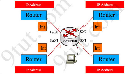
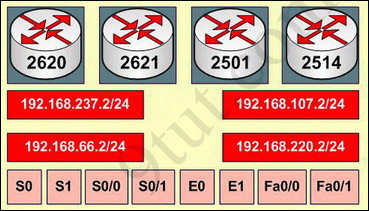
You have been hired by Specialty Hardware Incorporated to document the layout of the network. Complete the following tasks:? Complete the network topology shown in the graphic by dragging the labels below with the appropriate router types, interface types, and IP addresses to the graphic . Find the information you need by using the router console attached to the R-CENTER router.
Answer and explanation:
This is the simplest lab question in four labs you see in the real CCNA exam. First we should identify the types of these routers by using the show cdp neighbors command:
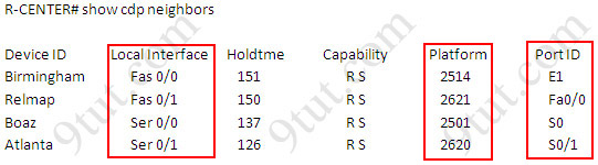
There are 3 columns we should pay more attention to:
+ Local Interface: the interface on the device you are using "show cdp neighbors" command. In this case it is the interface of R-CENTER router
+ Platform: the platform of neighbor device
+ Port ID: the neighbor device's port or interface on which the CDP packets are multicast
From the exhibit, the "Local Interface", "Platform" and "Port ID" columns, we can identify where these four routers should be placed and their corresponding associated ports
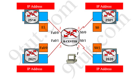
Finally, use the show running-config command to find out the ip addresses of four interfaces on R-CENTER
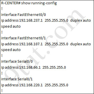
And we can easily assign corresponding ip addresses to four neighbor routers, which are on the same network with R-CENTER router's interfaces
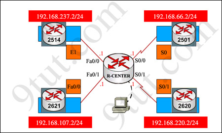
Please remember in the real CCNA Exam the routers' types, ip addresses and interfaces may be different! So make sure you understand how it works.