SIM 1 : EIGRP
After adding P4S2 router, no routing updates are being exchanged between P4S1 and P4S2. All other inter connectivity are woking properly. The task is to indentify the fault(s) and correct the router config to provide full conectivity between the routers. All passwords on all routers is Cisco. Ip address in the pics below :


Click host G to config the router in the pop-up CLI.
We see AS numbers are different for P4S1 and P4S2 router. We should edit AS number :
P4S2(config)#no router eigrp 22
P4S2(config)#router eigrp 212
P4S2(config-router)#no auto-sum
P4S2(config-router)#net 192.16.60.0
P4S2(config-router)#net 192.16.77.0
P4S2(config-router)#end
P4S2#copy run start
keyword "no auto-sum" for the router advertise major network. In this lap is class C.
P4S1 not yet advertised 192.168.77.0 network, we should adddition in:
P4S1(config)#router eigrp 212
P4S1(config-router)# net 192.168.77.0
P4S1(config-router)#end
P4S1# copy run start
Finally, on P4S2, we need enter "show ip route and ping" command for sure that eveything ok.
SIM 2 : RIP

Central Florida Widgets recently installed a new router in their office. Complete the network installation by performing the initial router configurations and configuring RIPV2 routing using the router command line interface (CLI) on the R2-RC.
Name of the router is R2-RC
Enable-secret password is cisco1
The password to access user EXEC mode using the console is cisco2
The password to allow telnet access to the router is cisco3
IPV4 addresses must be configured as follows:
Ethernet network 209.165.202.128/27 - router has last assignable host address in subnet
Serial network is 192.0.2.16/28 - router has last assignable host address in the subnet.
Interfaces should be enabled.
Router protocol is RIP V2
1) Name the router:
Router>enable
Router#configurate terminal
Router(config)#hostname R2-RC
2) Set secret password:
R2-RC(config)# enable secret cisco1
3) Set password for the console:
R2-RC(config)#line console 0
R2-RC(config-line)#password cisco2
R2-RC(config-line)#login
R2-RC(config-line)#exit
4) Set the Telnet password:
R2-RC(config)#line vty 0 4
R2-RC(config-line)#password cisco3
R2-RC(config-line)#login
R2-RC(config-line)#exit
5) Assign IP address for Ethernet interface (Fa0/0):
The Ethernet network 209.165.202.128/27 has:
Increment:32 (/27 = 255.255.255.224 or 1111 1111.1111 1111.1111 1111.1110 0000)
Network address: 209.165.202.128
Broadcast address: 209.165.202.159 (because 128 + 32 - 1 = 159)
Therefore the last assignable host address in this subnet is 209.165.202.158 and we will assign it to Fa0/0 interface with these commands:
R2-RC(config)# interface fa0/0
R2-RC(config-if)#ip address 209.165.202.158 255.255.255.224
R2-RC(config-if)#no shutdown
R2-RC(config-if)#exit
6) Assign IP address for Serial interface (S0/0/0):
Serial network 192.0.2.16/28 has:
Increment:16 (/28 = 255.255.255.240 or 1111 1111.1111 1111.1111 1111.1111 0000)
Network address: 192.0.2.16
Broadcast address: 192.0.2.31 (because 16 + 16 - 1 = 31)
So the last assignable host address in this subnet is 192.0.2.30. Finally we assign it to s0/0/0 interface:
R2-RC(config)# interface s0/0/0
R2-RC(config-if)#ip address 192.0.2.30 255.255.255.240
R2-RC(config-if)#no shutdown
R2-RC(config-if)#exit
7) Configure RIP v2 routing protocol:
R2-RC(config)#router rip
R2-RC(config-router)#version 2
R2-RC(config-router)#network 209.165.202.128
R2-RC(config-router)#network 192.0.2.16
R2-RC(config-router)#end
R2-RC#copy running-config startup-config
SIM 3 : NAT SIM
Question:
A network associate is configuring a router for the weaver company to provide internet access. The ISP has provided the company six public IP addresses of 198.18.184.105 198.18.184.110. The company has 14 hosts that need to access the internet simultaneously. The hosts in the company LAN have been assigned private space addresses in the range of 192.168.100.17 – 192.168.100.30 .

CLICK ON IMAGE TO VIEW

The following configuration translates between inside hosts (Weaver LAN) addressed from 192.168.100.16 /28 network (192.168.100.17 – 192.168.100.30) to the globally unique pool of address provided by ISP 198.18.184.105 – 198.18.184.110 /29.
Weaver>enable
Weaver#configure terminal
Before starting the NAT configuration verify that router hostname currently configured is weaver. If not change hostname to Weaver using the command
Router(config)#hostname weaver
Step1: Create an access-list to match all the Weaver LAN address that need to be the candidates for NAT translations
Weaver(config)#access-list 10 permit 192.168.100.16 0.0.0.15
Step2: Create a NAT Pool with pool name isp_adr and specify the pool address range provided by ISP with their netmask.
Weaver(config)#ip nat pool isp_adr 198.18.184.105 198.18.184.110 netmask 255.255.255.248
Step3: Packets that match access-list 10 will be translated to an address from the pool called "isp_adr".
Overload keyword specify to use Port based NATing to support all the Weaver LAN address range.
Weaver(config)#ip nat inside source list 10 pool isp_adr overload
SIM Question already provides that appropriate interfaces have been configured for NAT Inside and NAT Outside statements.
For your information configuration would have been like this
Weaver(config)#interface fastethernet 0/0
Weaver(config-if)#ip nat inside
Weaver(config)#interface serial 0/0
Weaver(config-if)#ip nat outside
Functionality Test:
Our requirements are to allow the hosts (Weaver LAN) the ability to communicate with the Internet. For this test, we ping the Internet device (ISP router S0/1) from Host for testing.
Step1:
Go to host for testing:
C:\>ping 192.0.2.114
PING should be success to 192.0.2.114 since SIM question provides that static route is already configured on router.
Step2:
On console of router (Weaver) :
Issue show ip nat translation command to verify the NAT translations.
Sample output:
Considering host for testing IP address is 192.168.100.17
weaver# show ip nat translation
Pro Inside global Inside local Outside local Outside global
icmp 198.18.184.105:434 192.168.100.17:434 192.0.2.113:434 192.0.2.114:434
icmp 198.18.184.105:435 192.168.100.17:435 192.0.2.113:435 192.0.2.114:435
icmp 198.18.184.105:436 192.168.100.17:436 192.0.2.113:436 192.0.2.114:436
icmp 198.18.184.105:437 192.168.100.17:437 192.0.2.113:437 192.0.2.114:437
icmp 198.18.184.105:438 192.168.100.17:438 192.0.2.113:438 192.0.2.114:438
Drag the appropriate device icons to the labeled Device
Drag the appropriate connections to the locations labeled Connections.
Drag the appropriate IP addresses to the locations labeled IP address (Hint: use the given host addresses and Main router information)
To remove a device or connection, drag it away from the topology.
Use information gathered from the Main router to complete the configuration of any additional routers. No passwords are required to access the Main router . The config terminal command has been disabled for the HQ router. The router does not require any configuration.
Configure each additional router with the following
Configure the interfaces with the correct IP address and enable the interfaces.
Set the password to allow console access to consolepw
Set the password to allow telnet access to telnetpw
Set the password to allow privilege mode access to privpw
Note: Because routes are not being added to the configurations, you will not be able to ping through the internetwork.
All devices have cable autosensing capabilities disabled.
All hosts are PC’s


ANSWER:

The question tells us that they are 3 routers and 1 Switch.
Drag the appropriate device icons to the labeled Device
Device Router (1) and Router (2) are connected to main router directly.
We can confirm this because the other Device labeled has Fa 0/2 and Fa 0/4 interfaces therefore this device is a switch.
Drag the appropriate connections to the locations labeled Connections.
1. The Main router is connected over serial link to Router (2) because on Router (2) the exhibit provide S 0/0 IP address icon towards Main router.
2. Router (1) is connected to Main router using a crossover cable. We require a crossover cable to connect two similar devices.
3. To connect host A directly to Router (1) fast ethernet 0/1 we need a crossover cable
4. Straight-through cable is used to connect a router (2) and switch together.
Drag the appropriate IP addresses to the locations labeled IP address (Hint: use the given host addresses and Main router information)
Host A IP address given 192.168.152.129 /28.
Host C IP address given 192.168.152.225 /28
/28 = 11111111. 11111111.11111111.11110000
= 255.255.255.240
Subnet mask is 255.255.255.240
Various subnet networks and its valid IP address ranges for the above subnet mask
1 – 15
16 – 31
32 – 47
48 – 63
64 – 79
80 – 95
96 – 111
112 -127
128 – 143 (Host A IP address is part of this subnet network IP address range, So Router (1)
Fa 0/1 address is 192.168.152.142)
144 – 159
160 – 175
176 – 191
192 – 207
208 – 223
224 – 239 (Host C IP address is part of this subnet network IP address range, Router (2)
Fa 0/0 address is 192.168.1.238)
240 – 255
Use the console of Main router and issue show running-config command at enable mode to verify the existing IP address configured on Main router Serial interface so has to identify the Network used in connecting Router (2) over serial link and depending on the network choose the appropriate IP address for S0/0 Router(2).
Similarly verify the Fast Ethernet interface IP address configuration on main router and select a IP address for Router (1) fa 0/0 it should be from same network address range.
Configure Router (1) and Router (2) with the following configuration:
Configure the interfaces with the correct IP address and enable the interfaces.
Router (1): Configuration
Router1>enable
Router1#configure terminal
Router1(config)#interface fa 0/0
Assigns IP address to Fa 0/0 and correct subnet mask
Router1(config-if)#ip address 192.168.152.190 255.255.255.240
Enables the interface
Router1(config-if)#no shutdown
Router1(config-if)#interface fa 0/1
Assigns IP address to Fa 0/1 and correct subnet mask
Router1(config-if)#ip address 192.168.152.142 255.255.255.240
Enables the interface
Router1(config-if)#no shutdown
Set the console, telnet and privilege mode access password as follows
Console: consolepw ; Telnet: telnetpw ; Privilege mode: privpw
To set console password
Router1(config)#line console 0
Router1(config-line)#password consolepw
Router1(config-line)#login
Router1(config-line)#exit
To set telnet password
Router1(config)#line vty 0 4
Router1(config-line)#password telnetpw
Router1(config-line)#login
Router1(config-line)#exit
To set privilege mode password
Router1(config)#enable password privpw
Router (2): Configuration
Router2>enable
Router2#configure terminal
Router2(config)#interface fa 0/0
Assigns IP address to Fa 0/0 and correct subnet mask
Router2(config-if)#ip address 192.168.152.238 255.255.255.240
Enables the interface
Router2(config-if)#no shutdown
Router2(config-if)#interface serial 0/0
Assigns IP address to serial 0/0 and correct subnet mask
Router2(config-if)#ip address 192.168.152.174 255.255.255.240
Enables the interface
Router2(config-if)#no shutdown
Set the console, telnet and privilege mode access password as follows
Console: consolepw ; Telnet: telnetpw ; Privilege mode: privpw
Similar configuration needs to be done for Router (2) to set the passwords for console, telnet and privilege mode as we did for Router(1).
Notice : after finished all config router, you must use "copy running-confg startup-config" command. If you dont use that, you will zero point !!!
SIM 5: Drag and Drop 2
Question: ( Source : 9tut.com)
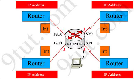
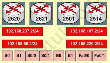
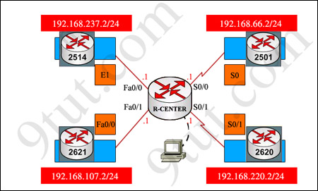
You have been hired by Specialty Hardware Incorporated to document the layout of the network. Complete the following tasks:? Complete the network topology shown in the graphic by dragging the labels below with the appropriate router types, interface types, and IP addresses to the graphic . Find the information you need by using the router console attached to the R-CENTER router.
Answer and explanation:
This is the simplest lab question in four labs you see in the real CCNA exam. First we should identify the types of these routers by using the show cdp neighbors command:
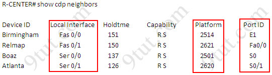
There are 3 columns we should pay more attention to:
+ Local Interface: the interface on the device you are using "show cdp neighbors" command. In this case it is the interface of R-CENTER router
+ Platform: the platform of neighbor device
+ Port ID: the neighbor device's port or interface on which the CDP packets are multicast
From the exhibit, the "Local Interface", "Platform" and "Port ID" columns, we can identify where these four routers should be placed and their corresponding associated ports
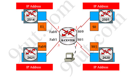
Finally, use the show running-config command to find out the ip addresses of four interfaces on R-CENTER
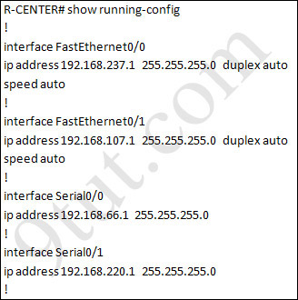
And we can easily assign corresponding ip addresses to four neighbor routers, which are on the same network with R-CENTER router's interfaces
Please remember in the real CCNA Exam the routers' types, ip addresses and interfaces may be different! So make sure you understand how it works.

great shares...tq very much bro
ReplyDelete